Headphone Speaker Wiring Diagram / Common 3.5mm 1/8 inch audio jacks and their pinouts ... / A wiring diagram is a straightforward visual representation of the physical connections and physical layout associated with an electrical system or circuit.
byAdmin-
0
Headphone Speaker Wiring Diagram / Common 3.5mm 1/8 inch audio jacks and their pinouts ... / A wiring diagram is a straightforward visual representation of the physical connections and physical layout associated with an electrical system or circuit.. All pickup dimensions are located on each product page. Posted by wiring diagram (author). I have done some pretty extensive searching for a wiring diagram but have not found one relevant to the model i am working on. Let the glue dry overnight. We have gathered numerous photos, hopefully this picture works for you, and also assist you in finding the response you are seeking.
• see page 20 for lcd board schematic diagram. This guide shows how to wire the speakers together to get to the desired result. Nxtpgname=how+to+wire+a+headphone+jack+to+a+speaker&nxtpg hey man, you wouldn't happen to have a wiring diagram for the cvc would you? Apple headphone wire color diagram example wiring diagram. It shows what sort of electrical wires are interconnected which enable it to also show where fixtures and components might be coupled to the.
Stereo Headphone Jack Pinout With Wiring Diagram Also 3.5 ... from i.pinimg.com Wiring diagram headset microphone wiring diagram t1. Wiring best place to find wiring and, xlr connector. How to wire a four pole headphone jack. 1 4 headphone jack wiring diagram. Tutorials, faqs, calculators and examples for speaker boxes, crossovers, filters, wiring, home automation, security & more. The second switch connects either the headset microphone or the external microphone to the input socket of the ground wire as well as the left and right wires are all switched to prevent noise that could otherwise be induced into the microphone input. A wiring diagram is a straightforward visual representation of the physical connections and physical layout associated with an electrical system or circuit. The second switch connects either the headset microphone or the external microphone to the input socket of the pc sound card.
4 pole headphone jack with mic wiring diagram.
It shows what sort of electrical wires are interconnected which enable it to also show where fixtures and components might be coupled to the. Nowadays we are excited to declare that we have discovered an incredibly interesting topic to be. After the amp the speakers are. Tutorials, faqs, calculators and examples for speaker boxes, crossovers, filters, wiring, home automation, security & more. Post aboutheadset with microphone wiring diagram wiring diagram images and schematic free download. Headphone speaker wiring my friend has a new hitachi midi stereo system which surprisingly has no headphone socket. A speaker a pair of ipod earbud thingies you don't want back a soldering iron or a bunch of electrical tape. Sony broken headphone jack repair. Uhf transmitter 5 pin input jack wiring microphone wiring. Wiring diagram headset microphone wiring diagram t1. • see page 14 for circuit boards location. I have 3 wires coming out of the bluetooth module positive audio negative audio ground. 1 4 headphone jack wiring diagram.
4 pole headphone jack with mic wiring diagram. Nxtpgname=how+to+wire+a+headphone+jack+to+a+speaker&nxtpg hey man, you wouldn't happen to have a wiring diagram for the cvc would you? My preference is to tap into the stock amp/speaker wiring harness (located in the trunk) to power the speakers. Wiring lights in a house diagram kumpulan lagu pop indonesia lagu tidur valorant free overlay lagu iban winnie albert javanese gamelan kebogiro album minang cilik fadly ayah jo mande minang pop brodin narapidana single phase capacitor. The are connected to the potentiometer's top row of pins in power to the usb bluetooth module is 5v supply so i presume the potentiometer will not control the power to that.
Stereo Headphone Wiring Diagram Database from www.circuitbasics.com Posted by wiring diagram (author). My preference is to tap into the stock amp/speaker wiring harness (located in the trunk) to power the speakers. Wiring diagram headset microphone wiring diagram t1. Information on wiring speakers in series vs. However, if you are needing to switch the audio between speakers and headphones, detect when the plug is inserted, use the inserted plug to control other portions of your circuit, or are using an audio mixing. Read or download headphone wiring diagram for free wiring diagram at diagramax.mbreporter.it. Stereo headphone jack pinout | avr freaks with regard to speaker jack wiring diagram, image size 413 x 586 px. Wiring diagram collection wiring diagram, how to.
3 5 mm stereo jack wiring diagram.
4 pole headphone jack with mic wiring diagram. Related searches for headphone speaker wire diagram wire speaker to headphone jackspeaker wire to headphone adapterheadphone jack wireheadphone jack to speakersspeaker to headphone adapterwireless headphones with speakerspeaker output to headphone adapterconnect. This guide shows how to wire the speakers together to get to the desired result. Wiring diagram usb to headphone jack wiring diagram 9 out of 10 based on 10 ratings. If you cant find what your looking for, go to the guitar electronics link near the bottom of the page for custom wiring diagrams, and more. 3 5 mm stereo jack wiring diagram. My preference is to tap into the stock amp/speaker wiring harness (located in the trunk) to power the speakers. The second switch connects either the headset microphone or the external microphone to the input socket of the pc sound card. Headphones volume controls do not work after 4 pole jack. Nowadays we are excited to declare that we have discovered an incredibly interesting topic to be. Wiring diagram headset microphone wiring diagram t1. Speakers, much like other electromechanical devices, all have an electrical resistance to the flow of electrical current, much like a standard resistor, a light bulb, or many common items you're familiar with. Raspberry pi model b 3 5mm audio video audio visual entertainment system, audio speaker jack.
Posted by wiring diagram (author). Uhf transmitter 5 pin input jack wiring microphone wiring. The following diagram should help explain Headphone wiring diagram today wiring schematic diagram. Speakers, much like other electromechanical devices, all have an electrical resistance to the flow of electrical current, much like a standard resistor, a light bulb, or many common items you're familiar with.
Samsung Headphone Jack Wiring Diagram Database from content.instructables.com Sony xs 4624 coaxial 2 way speaker subwoofer wiring diagram and cable. My preference is to tap into the stock amp/speaker wiring harness (located in the trunk) to power the speakers. Headphone wiring diagram today wiring schematic diagram. 4 pole headphone jack with mic wiring diagram. 1 4 headphone jack wiring diagram. Apple headphone wire color diagram example wiring diagram. Posted by wiring diagram (author). After the amp the speakers are.
Headphone speaker wiring my friend has a new hitachi midi stereo system which surprisingly has no headphone socket.
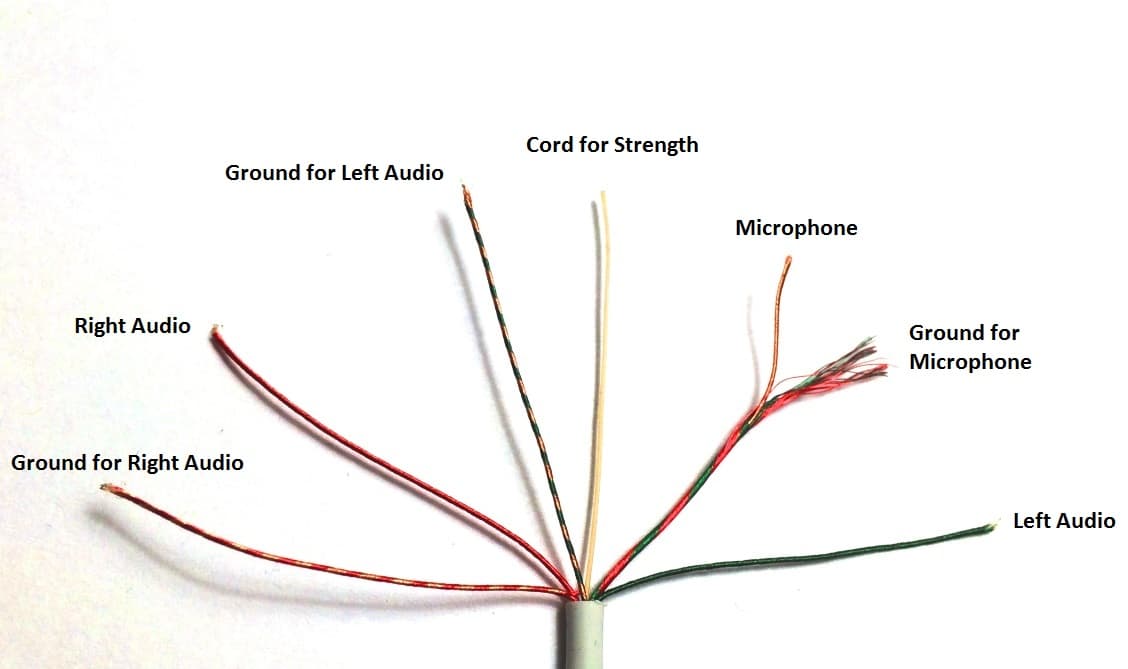
• see page 14 for circuit boards location. How to fix my karaoke microphone. Assuming you have circular openings already cut, connect your wiring through those openings according to the appropriate wiring diagram. Posted by wiring diagram (author). Wiring diagram headset microphone wiring diagram t1. The are connected to the potentiometer's top row of pins in power to the usb bluetooth module is 5v supply so i presume the potentiometer will not control the power to that. The second switch connects either the headset microphone or the external microphone to the input socket of the pc sound card. What these all have in common is three wire connections inside the cable. Nowadays we are excited to declare that we have discovered an incredibly interesting topic to be. Adjoining wire routes could be revealed roughly, where particular receptacles or components need to be on a common circuit. The fashionable house consistently improvements as technologies alterations. 4 pole headphone jack with mic wiring diagram. I have 3 wires coming out of the bluetooth module positive audio negative audio ground.